Analog Outputs
See also: General I/O Configuration

|
Analog I/O in the OCS |
Note: See the datasheet for the model being used for jumper settings, if used. Refer to the Documentation Page to find the datasheet.
The analog outputs on OCS devices provide high resolution voltage or current outputs. The voltage or current selection is controlled with jumpers and configuration settings in Cscape.
Note: Each channel can be separately configured for voltage or current mode. When the controller is stopped, the operation of each output is configurable. The outputs can hold the state they were in before the controller stopped or they can go to a predetermined value. By default, analog outputs are set to a value of zero (0).
Analog Output Configuration
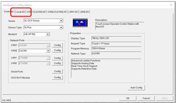
Home > Hardware Configuration [Select Device Type/Model#] > Local I/O Tab > I/O/Config Button > Module Setup > Analog Out
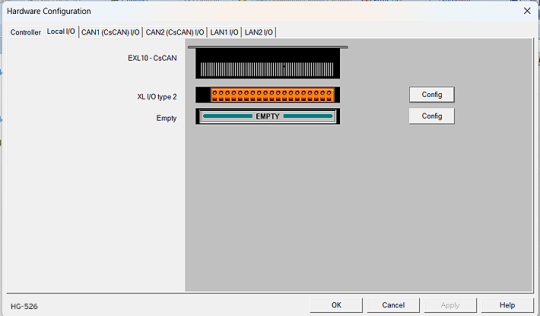
Select Hardware Configuration from the Home menu and ensure that the correct Device Type and Model# are selected. Then select the Local I/O tab.
After selecting Local I/O, select the Config button next to the I/O connector.
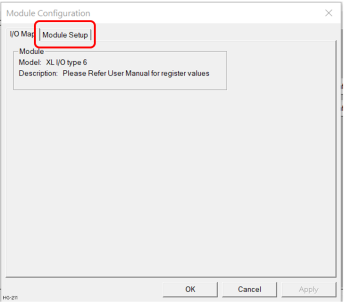
The Module Configuration screen will appear, select the Module Setup tab. See below.
The Module Setup allows a user to configure four types of I/O.
Note: Not all controllers offer all four types. Refer to the controller's datasheet on the Horner website's Documentation Page for more information regarding specific models.
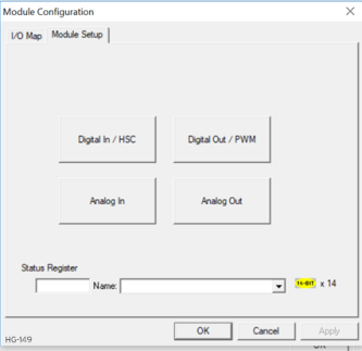
Select Analog Out to open the Analog Output Configuration dialog:
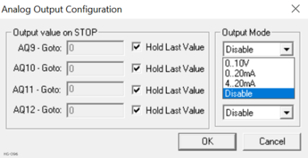
Output value on Stop - Contains items that allow the user to specify how the analog output channels behave when the controller is stopped. The outputs can either hold their value or default to a value when the controller is stopped.
Output Mode - Select the operating modes for each of the analog outputs. The modes include the following:
-
0..10V
-
0..20mA
-
4..20mA
-
Disable
Return to the Top: Analog Outputs